
AI robots are moving from pilots to daily operations in warehouses, factories, and high-visibility public spaces. As fleets scale, the battery pack becomes a strategic bottleneck: it directly impacts uptime, safety acceptance, integration speed, and total lifecycle cost. For technical buyers and distributors, the biggest friction points are familiar: exaggerated specs, limited real test data, and uncertainty around certifications and documentation.
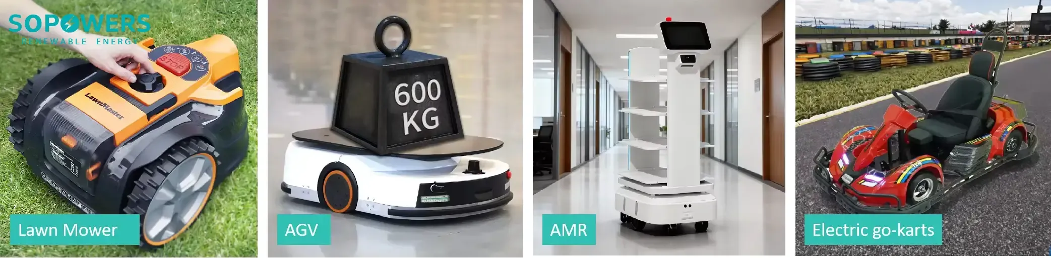
Below is an application-driven, list-style guide to a 15Ah, 15S1P, 48V LFP design with 5C capability, focusing on the engineering details that matter in real deployments.
1) Start with the duty cycle: what the robot actually asks from the pack
Before locking in an AI robot battery pack specification, confirm the operating profile. Most field issues come from mismatch, not cell quality.
- Power profile (average vs peak)
- AMRs often run modest average power with short acceleration peaks.
- AGVs towing loads may demand longer high-current segments.
- Charging strategy
- Opportunity charging (short, frequent top-ups) vs long overnight charging.
- Swapping vs onboard charging access constraints.
- Environment
- Climate-controlled warehouses, chilled zones, or hot outdoor lanes.
- Integration expectations
- The pack is not only power, it is data: SOC/SOH and alarms must reach the robot controller via CAN / RS485 communication.
Sopowers’ process emphasizes pre-delivery solution matching and technical confirmation (capacity, voltage, power rating, feasibility), then factory testing and consistency screening, followed by after-delivery troubleshooting support when real usage reveals edge cases, especially considering the 5C discharge capability of LFP batteries, renowned for their intrinsic safety, even withstanding impacts up to 120 km/h without explosion or sustained fire.
2) Why 15Ah + 15S1P / 48V architecture is a practical baseline for robots
A 15S1P / 48V architecture aligns naturally with common 48V-class motor drives and DC-DC ecosystems. With LFP (LiFePO4) chemistry, it also prioritizes safety and predictable aging.
Quick spec snapshot (illustrative engineering baseline)
| Item | Typical value for this design concept | Why it matters in robots |
|---|---|---|
| Chemistry | LFP (LiFePO4) battery pack | Strong safety narrative, long cycle life |
| Configuration | 15S1P 48V battery pack | Fits 48V drivetrains, reduces current vs 24V |
| Capacity | 15Ah 48V battery | Compact module size, swappable-friendly |
| Nominal energy | ~720 Wh (48 V x 15 Ah) | Basis for energy (Wh) / runtime estimation |
| Discharge target | Up to 5C (~75 A) continuous (design-dependent) | Supports acceleration, ramps, payload spikes |
| Peak behavior | Higher short peaks possible with limits | Helps avoid undervoltage cutoffs |
| Typical mass | Often ~5 to 7 kg class (pack-level) | Impacts robot dynamics and swap ergonomics |
Energy and runtime estimation (useable energy, not nameplate)
A realistic runtime estimate uses usable energy, not the full nominal value (many fleets limit SOC window to extend cycle life). A simple estimate:
- Runtime (hours) = usable Wh / average W
Example bar chart (illustrative, assuming ~650 Wh usable):
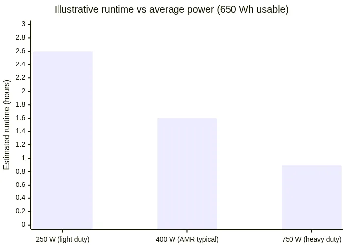
Use this only as a first-pass. For procurement decisions, the pack should be validated against the robot’s real duty cycle (stop-and-go motion, idle time, slopes, and any regenerative braking behavior).
3) Power delivery that feels stable: peak current, low voltage sag, and BMS limits
In robots, “power” is not just a C-rate claim. It is the combination of cell selection, copper/busbar design, BMS current limits, and thermal headroom.
- High power output / peak current
- For 15 Ah, 5C implies ~75 A continuous as a design target (cell and thermal dependent).
- Short bursts can be higher (often used for acceleration or ramp starts), but should be explicitly time-limited and temperature-limited.
- Low internal resistance / low voltage sag
- Lower pack resistance reduces voltage droop under load, helping motor controllers stay out of undervoltage protection.
- It also improves SOC estimation stability when the robot alternates between idle and high load.
- BMS architecture: protections + data
- Minimum expectations:
- Over/under-voltage (cell and pack), over-current, short-circuit
- Over/under-temperature for both charge and discharge
- Cell balancing
- Data points that reduce field troubleshooting time:
- SOC, SOH, cycle count
- Pack voltage/current, multiple temperatures
- Fault codes and event logs (over-current events, low-voltage events)
- Minimum expectations:
If your supplier cannot provide clear current derating logic (temperature and SOC boundaries), it becomes difficult to predict real-world performance without extensive in-house testing.
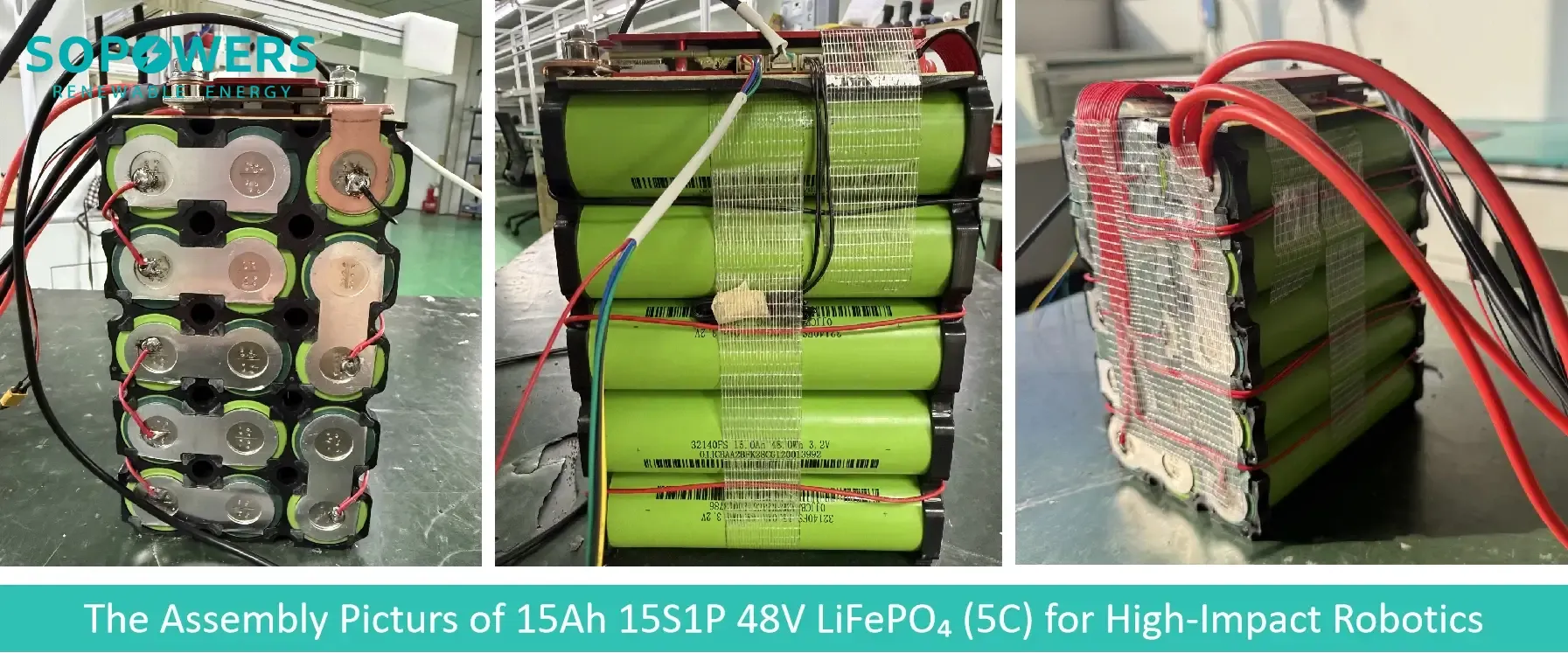
4) Integration details that decide project speed: connectors, comms, and pack form factor
For many OEMs, the “battery integration tax” is higher than the battery cost. Three areas decide whether the integration takes weeks or quarters.
- Connectors & interfaces (charge/discharge, comms)
- Power connectors should match continuous and peak current, mating cycle targets, and any sealing/IP requirements.
- Signal connectors should be mechanically robust and serviceable (a separate diagnostic port often saves time).
- CAN / RS485 communication
- CAN is common for mobile platforms because it is robust in electrically noisy environments.
- RS485 is widely used for simpler systems and long cable runs.
- Confirm upfront:
- Protocol expectation (for example, CANopen or a custom mapping)
- Message list: SOC/SOH, limits, alarms, temperatures, remaining runtime estimate
- Update rate requirements for fleet monitoring
- Pack form factor, size & weight
- Keep center of gravity low for stability (especially for tall service robots).
- For swappable designs, ergonomics matter: handles, guide rails, and latches must be treated as first-class requirements, not afterthoughts.
Sopowers typically aligns these integration details during the solution matching stage, then validates them through prototype builds and consistency screening before shipment.
5) Safety-first engineering: thermal control, mechanical protection, and abuse testing
In public-facing and industrial environments, a battery pack must be designed to fail safely. LFP chemistry is favored here because of its strong thermal stability and reduced thermal runaway risk compared with more reactive chemistries.
Thermal management / temperature rise control
Even with LFP, high-rate discharge produces heat. Practical design measures include:
- Heat spreading via metal enclosure walls and internal plates
- Temperature sensors placed to capture worst-case hot spots
- Derating logic in BMS to prevent runaway heating
- Robot-level airflow planning (don’t trap the pack in a sealed insulated bay)
For cold environments, pack behavior must be specified clearly (charge limits below 0 C are common). If the application includes cold storage, low-temperature design considerations become non-optional (see Sopowers’ engineering context in low-temperature battery basics).
Mechanical protection: enclosure, damping, insulation
Safety is not only chemistry. For mobile robots that may collide with equipment, key measures include:
- Rigid enclosure (often aluminum) with reinforcing ribs
- Internal damping to absorb impact energy and reduce vibration fatigue
- Cell isolation and insulation layers to reduce internal short risk
- Defined venting paths that route gases away from sensitive electronics
This is where a safety-first / no-thermal-runaway narrative becomes credible: the goal is controlled behavior even under severe mechanical events. In Sopowers’ stated positioning for robot packs, LFP designs are intended to avoid explosion or sustained fire even in extreme impact scenarios (described as up to 120 km/h impact severity), supported by mechanical protection and protective electronics design choices.
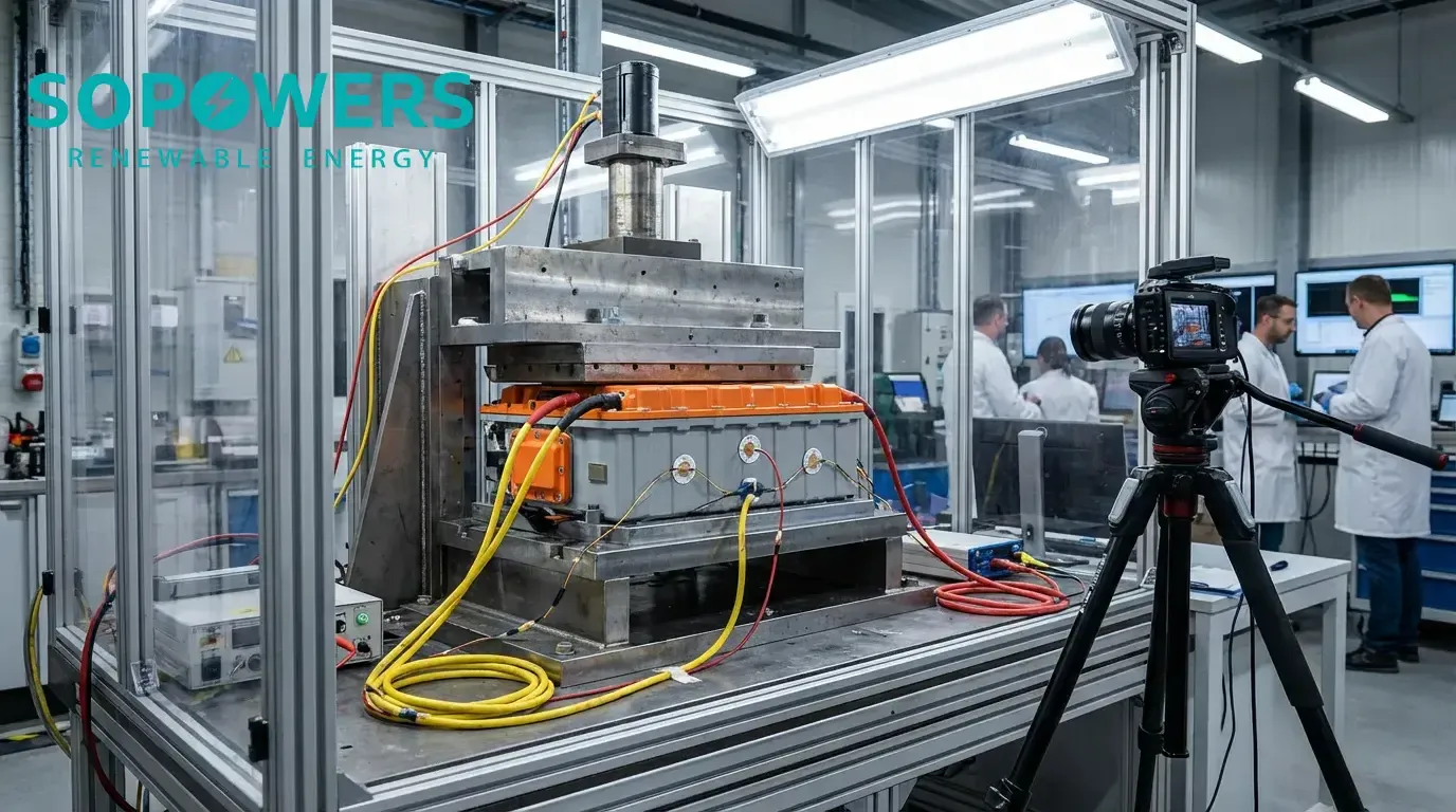
Abuse testing: crush, penetration, impact
When buyers ask, “How do we know it is safe?”, the best answer is: align design validation with recognized standards and document the results.
Authoritative references for what those tests look like include:
- UN 38.3 transport testing framework
- IEC 62619 industrial lithium battery safety
- UL 2271 battery packs for light electric vehicle applications
- UL 2580 electric vehicle battery safety
6) A buyer’s checklist: what to request from a supplier (and how Sopowers supports)
Use this as a practical procurement checklist to reduce surprises.
| What to confirm | What to ask for | Why it reduces risk |
|---|---|---|
| Real discharge capability | Continuous/peak current limits vs temperature and SOC | Prevents “paper C-rate” surprises |
| Energy and runtime | Usable Wh assumption and duty-cycle model inputs | Avoids undersized fleets and downtime |
| BMS telemetry | CAN or RS485 message list, fault codes, logging | Speeds robot integration and debugging |
| Connectors | Rated current, mating cycle target, IP needs | Prevents heat, arcing, and service issues |
| Mechanical design | Mounting method, vibration strategy, insulation stack-up | Prevents fatigue failures and internal shorts |
| Safety validation | UN 38.3 status, industrial safety test plan | Supports shipping and compliance planning |
| Consistency controls | Factory testing, cell matching, batch screening | Stabilizes fleet-level performance |
Sopowers’ differentiation is process-driven: pre-sales feasibility confirmation, in-production testing and screening, and post-delivery technical support with root-cause analysis. For technical buyers who are tired of exaggerated claims, this “show the data, not slogans” approach is often the deciding factor.


